The most common question when designing an MBBR system: “how big does the reactor need to be?” Go too small and effluent misses permit limits. Too large and you’ve wasted CAPEX on unnecessary tank volume and media.
This guide walks through the industry-standard Surface Area Loading Rate (SALR) method with a worked example for a 7,000 m³/day municipal plant. By the end, you’ll be able to run your own preliminary sizing with just influent data and a calculator.
Key Design Parameters
Before we calculate, here are the five parameters that govern any MBBR design.
| Parameter | Symbol | Unit | Typical Range | What It Means |
|---|---|---|---|---|
| Surface Area Loading Rate | SALR | g/m²/day | 5–25 (BOD), 0.5–1.5 (NH&sub3;-N) | How much pollutant per m² of media surface per day |
| Carrier Specific Surface Area | SSA | m³/m³ | 500–1000+ | Biofilm surface area per m³ of media |
| Fill Ratio | — | % | 30–55% (up to 65% with aeration upgrade) | % of empty tank volume occupied by media |
| Hydraulic Retention Time | HRT | hours | 2–6 | Average time wastewater spends in the reactor |
| Oxygen Requirement | — | kg O&sub2;/kg BOD | 1.2–2.0 | O&sub2; needed per kg BOD removed |
Source: Download from [Washington State Department of Ecology MBBR Design Spreadsheet].
SALR is the primary parameter — it directly determines media quantity.
SSA is media-specific (K1, K3, K5, and Mutag Biochip differ).
Fill ratio is a design choice affecting tank size and aeration energy.
HRT is the result of these choices, not an independent input — always verify it falls within the typical range.
The SALR Method
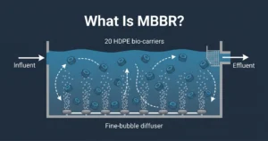
Unlike activated sludge (sized by F/M ratio or SRT), MBBR is limited by biofilm surface area — you can’t grow more biomass than the media surface can support. That’s why SALR, not volumetric loading, is the starting point.
SALR answers: “given your effluent target and temperature, how many grams of BOD can one square meter of media handle per day?”
The lower the SALR, the higher the removal — but the more media and tank volume required.
Design SALR Values at 15°C
| Treatment Objective | BOD Removal Target | Design SALR (g/m²/day) |
|---|---|---|
| High rate (roughing) | 75–80% | 25 |
| Normal rate | 85–90% | 15 |
| Low rate (high-quality effluent) | 90–95% | 7.5 |
| Tertiary nitrification | NH&sub3;-N > 90% | 0.5–1.5 |
For this guide, targeting >90% removal at 15°C, we’ll use SALR = 10 g/m²/day.
Step-by-Step MBBR Sizing
Design basis: 7,000 m³/day municipal wastewater, influent BOD₅ = 300 mg/L, target effluent ≤30 mg/L (>90% removal), K5 media (500 m²/m³), 50% fill ratio, 5 m depth.
Step 1: Calculate Daily BOD Loading
BOD Loading (kg/day) = Q (m³/day) × S₀ (mg/L) ÷ 1,000
= 7,000 × 300 ÷ 1,000
= 2,100 kg/day
(Reminder: 1 mg/L = 1 g/m³, so dividing by 1,000 converts grams to kilograms.) That’s 2,100 kg of BOD entering the system every day — the load our biofilm needs to handle.
Step 2: Select Design SALR → 10 g/m²/day
SALR = 10 sits between the standard low-rate (7.5) and normal-rate (15) values. Temperature affects this — at 20°C you could use a higher SALR, but it’s good practice to design for winter conditions. More on that below.
Step 3: Calculate Required Carrier Surface Area
Convert loading to grams: 2,100 kg/day × 1,000 = 2,100,000 g/day
Required Area (m²) = BOD Loading (g/day) ÷ SALR (g/m²/day)
= 2,100,000 ÷ 10
= 210,000 m²
> Media note: K5 provides ~500 m²/m³. K3 (>650 m²/m³) or Mutag Biochip (>1,000 m²/m³) would need less volume — smaller reactor, higher media cost.
Step 4: Calculate Carrier (Media) Volume
Carrier Volume (m³) = Required Area (m²) ÷ SSA (m²/m³)
= 210,000 ÷ 500
= 420 m³
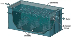
> Screen sizing note: Media dimensions determine retention screen slot width. For K5 (~15 mm), use 4–5 mm slots. [Retention screen guide →](/mbbr-system/mbbr-retention-screens/)
Step 5: Calculate Reactor Volume
Tank Volume (m³) = Carrier Volume ÷ Fill Ratio (decimal)
= 420 ÷ 0.50
= 840 m³
HRT (hours) = Tank Volume ÷ Q × 24 = 840 ÷ 7,000 × 24 = 2.88 hours ✓
~3 hours HRT is well within the typical range (2–6 h) and consistent with real-world designs. For reference, the Kerala Water Authority Ponnani Harbour plant operates at ~3.07 h at similar loading. If HRT falls below 1.5 h, increase tank volume (lower fill ratio or higher-SSA media). Above 6 h suggests over-design.
Step 6: Calculate Aeration Demand
For high-SRT MBBR systems, the standard design factor is approximately 1.5 kg O₂ per kg BOD removed (source: WA Ecology spreadsheet).
O₂ Demand = 2,100 × 1.5 = 3,150 kg/day
Convert to air flow — accounting for oxygen transfer efficiency. Fine bubble diffusers at 5 m depth: SOTE ≈ 12.3%.
Mass O₂ to supply = 3,150 ÷ 0.123 = 25,610 kg/day
Mass air needed = 25,610 ÷ 0.232 (O₂ in air) = 110,388 kg/day
Volume air = 110,388 ÷ 1.2 (air density) = 91,990 m³/day ≈ 64 m³/min
Also verify mixing energy (20–35 m³ air per m² of tank floor). The larger of biological vs. mixing requirements governs blower selection.
> Diffuser selection: Fine bubble disc diffusers achieve higher SOTE than coarse bubble, reducing blower energy costs over the life of the system. [Aeration diffuser types →](/aeration-diffusers/)
Temperature Correction
Temperature is one of the most overlooked factors. Biofilm activity decreases as temperature drops. The standard correction uses θ = 1.058:
SALR_T = SALR_20°C × 1.058^(T − 20)
| Design Temp (°C) | Activity Factor | Volume Impact vs 20°C |
|---|---|---|
| 5 | 0.43 | +133% |
| 10 | 0.57 | +75% |
| 15 | 0.75 | +33% |
| 20 | 1.00 | Reference |
| 25 | 1.33 | −25% |
| 30 | 1.76 | −43% |
For our example at 15°C: activity factor = 1.058^(15−20) = 0.75. A reactor sized at 20°C without correction would need 33% more volume to achieve the same performance at 15°C. At 10°C, the same plant needs 75% more tank volume.
Critical design rule (from the [ScienceDirect MBBR & IFAS review]): Use the lower temperature for sizing tank and carrier volume (biological activity is lowest). Use the higher temperature for calculating oxygen supply (demand is highest at high temperature).
Practical takeaway: Design for your coldest month’s average temperature. A cold-climate plant (10–12°C) needs roughly 75% more tank volume than the same plant in a warm climate.
Summary Table
| Parameter | Value | Unit |
|---|---|---|
| Daily BOD loading | 2,100 | kg/day |
| Design SALR (15°C) | 10 | g/m²/day |
| Media type | K5 | — |
| Required carrier surface area | 210,000 | m² |
| Required carrier volume | 420 | m³ |
| Fill ratio | 50 | % |
| Required tank volume | 840 | m³ |
| HRT | 2.88 | hours |
| O2 demand | 3,150 | kg/day |
| Design air flow | 64 | m³/min |
5 Common Design Mistakes
1. Ignoring temperature correction
Designing at 20°C for a 10°C winter plant. System meets targets 8 months, fails in cold weather.
Fix: Size tank volume for lowest temperature, aeration for highest.
2. Wrong SALR for the permit target
Using a high-rate SALR (25 g/m²/day) when the permit requires >90% removal. High-rate only removes 75–80%. Fix: Match SALR to your permit requirement, not your hope.
3. Fill ratio too high
Pushing fill above 55% without verifying aeration keeps media fluidized. Media settles, effective volume drops. Fix: Above 50%, check aeration carefully. Above 65%, specialized high-energy grids are needed.
4. Ignoring peak flow
Sizing on average flow alone. During wet weather, HRT drops below what biofilm needs.
Fix: Check HRT at peak flow (2–2.5× average). If below 1 hour, add equalization or increase tank volume.
5. Guessing blower size
Rule-of-thumb air-to-water ratios without actual SOTE waste energy or strand capacity.
Fix: Calculate O₂ demand as in Step 6, apply diffuser-specific SOTE.
Next Steps
You now have a preliminary MBBR design: 840 m³ reactor, 420 m³ K5 media, ~3 h HRT, ~64 m³/min air.
1. Verify with vendor media data — Certified SSA varies by manufacturer.
2. Design the aeration grid — Diffuser count, spacing, pipe sizing, blower.
3. Size retention screens — Slot width must match media.
4. Design anoxic/anaerobic mixing — For denitrification zones.
References: WA Ecology MBBR Design Spreadsheet; Kerala Water Authority Ponnani Harbour DPR; ScienceDirect — MBBR & IFAS Technology; Harlan Bengtson — McGraw-Hill MBBR Design Spreadsheets.