MBBR System
Complete Guide to Moving Bed Biofilm Reactor Technology
The Moving Bed Biofilm Reactor (MBBR) is a biological wastewater treatment process that uses free-floating plastic media to host active biofilm. Developed in Norway in the late 1980s, MBBR has become one of the most widely adopted biological treatment technologies worldwide — used in thousands of municipal and industrial plants across every continent.
Unlike conventional activated sludge (CAS) systems that rely on suspended biomass, MBBR grows biofilm on protected carrier surfaces inside the reactor. This simple difference gives MBBR several fundamental advantages: higher biomass concentration, smaller footprint, greater resilience to shock loads, and no sludge bulking issues.
This guide provides a comprehensive overview of the MBBR process, ranging from its principles to its applications—including its definition, working mechanism, required components, and suitable use cases.
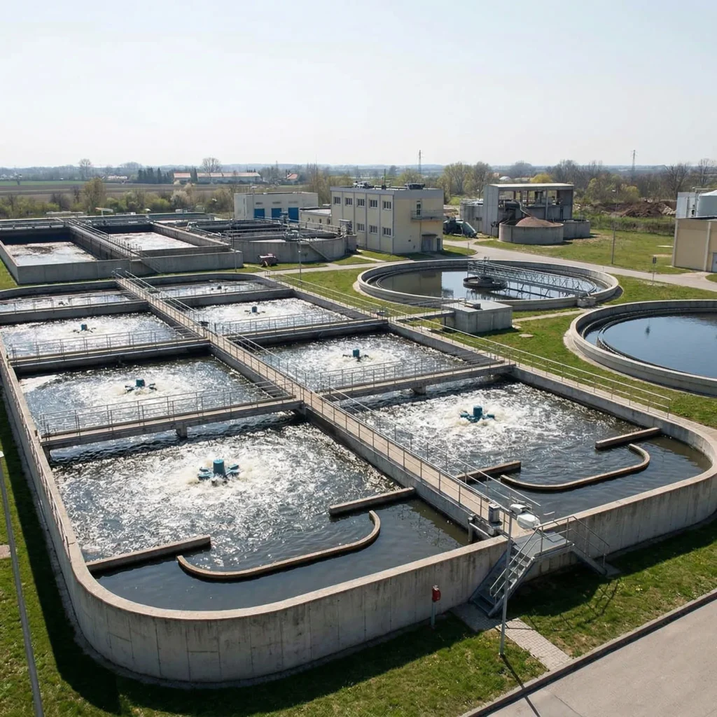
Position of MBBR in the Wastewater Treatment Process
MBBR is a secondary (biological) treatment technology. In a typical wastewater treatment plant, it sits after primary treatment and before final clarification / disinfection:
MBBR can also be integrated into existing plants as a retrofit upgrade — replacing or augmenting existing biological treatment capacity without building new tanks. This is one of its most common applications.
How the MBBR Process Works
The MBBR process is built on four fundamental principles:
1. Biofilm Carrier Media
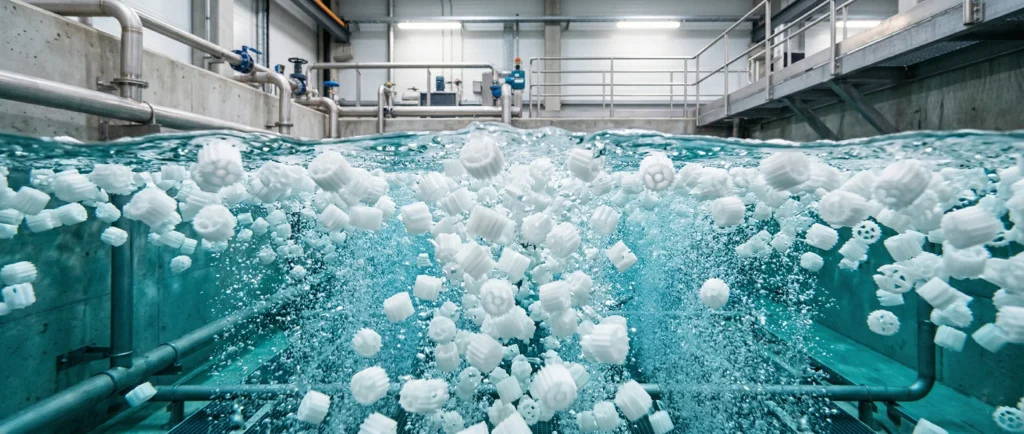
Small HDPE carriers (typically 7–25 mm) are added to the reactor at a filling ratio of 25–55%. Each piece provides a protected surface for microorganisms to attach and grow as biofilm. The media is the heart of the system — more surface area means more biological treatment capacity.
2. Continuous Fluidization
In aerobic zones, fine or coarse bubble aeration keeps the media moving through the water column. In anoxic/anaerobic zones, submersible mixers provide the necessary flow. This constant motion ensures every media surface is exposed to wastewater and oxygen.
3. Biofilm Growth & Activity
Microorganisms attach to the media surface and form a biofilm layer — typically 50–500 μm thick. The outer layer of the biofilm is aerobic (exposed to oxygen), while inner layers can be anoxic (enabling simultaneous nitrification and denitrification within a single carrier). Excess biofilm naturally shears off and is carried out with the effluent to be settled in the clarifier.
4. Media Retention
At the reactor outlet, retention screens (wedge wire, perforated, or cylindrical) prevent media from leaving the tank. Treated water passes through while media stays in the reactor.
Key advantage: Because the biofilm is fixed to the media and media stays in the reactor, the biomass concentration is independent of the clarifier performance. There is no sludge settling limitation — a fundamental constraint in activated sludge systems.
MBBR System Components
A complete MBBR system consists of four main components. Each must be designed to work with the others — the media size determines the screen slot width, the aeration design must match the media fluidization requirement, and the mixer power depends on the media filling ratio.
1. MBBR Bio Media (Core Component)
The biological carrier where biofilm grows. Available in K1, K3, K5, and Mutag Biochip designs, each suited to different wastewater profiles. Media selection determines treatment capacity, system stability, and operating cost.
2. Retention Screens
Installed at the reactor outlet to retain media while allowing treated water to pass through. Wedge wire panels are the industry standard for their self-cleaning properties and high open area. Slot width must match the selected media size.
3. MBBR Mixers
Submersible mixers installed in anoxic and anaerobic zones where aeration is not available. Gentle, low-shear hydrofoil propellers keep media suspended without stripping biofilm.
4. Aeration Diffusers
Fine bubble disc or tube diffusers supply oxygen and fluidize the media in aerobic zones. The aeration system must be designed to deliver both the oxygen demand and the mixing energy needed for media fluidization.
MBBR vs Conventional Activated Sludge (CAS)
Understanding the difference between MBBR and CAS helps in making the right technology choice. Here is a direct comparison:
| Parameter | MBBR | Conventional Activated Sludge (CAS) |
|---|---|---|
| Biomass form | Attached biofilm on media carriers | Suspended flocs in mixed liquor |
| Biomass concentration | Higher (MLVSS equivalent 5–15 g/L) | Limited by clarifier settling (2–4 g/L) |
| Footprint | 30–50% smaller for same treatment capacity | Larger — needs bigger tanks and clarifiers |
| Sludge settling | Not a factor — biomass held on media | Bulking and settling problems are a common operational issue |
| Shock load resistance | High — protected biofilm handles fluctuations well | Moderate — shock loads can upset the biological balance |
| Sludge production | Lower (longer sludge age, less excess sludge) | Higher — more sludge to handle and dispose |
| Retrofit / expansion | Excellent — add media to existing tanks to increase capacity | Difficult — typically requires new tank construction |
| Operator skill | Lower — less process control needed | Higher — requires careful SRT, F/M ratio control |
| Capital cost | Comparable or lower (smaller tanks, less civil work) | Higher for new builds; depends on clarifier design |
Design Considerations for an MBBR System
Designing an MBBR system requires balancing several interdependent parameters. The table below covers the most important factors:
| Parameter | Typical Range | Notes |
|---|---|---|
| Filling ratio | 25–55% | Higher fill → more capacity but more aeration/mixing energy needed. Max practical limit ≈60%. |
| Organic loading rate (OLR) | 5–20 kg COD/m³·d | Varies by media type and target effluent quality. Biochip handles the highest rates. |
| Hydraulic retention time (HRT) | 2–8 hours | Depends on influent strength and treatment target. Municipal: 3–6 h. Industrial: 6–12 h. |
| Dissolved oxygen (DO) | 2–4 mg/L (aerobic zone) | Higher DO → faster treatment but higher energy cost. 2 mg/L is typically sufficient. |
| Mixing energy (anoxic) | 5–15 W/m³ | Sufficient to keep media fully suspended without excessive shear on biofilm. |
| Screen slot width | 60–80% of media min. dimension | Smaller slots → better retention but risk clogging. Balance is critical. |
| Temperature | 5–35°C | Biological activity decreases at low temperature. Design for winter conditions. |
Table of Contents
Categories
Get the Perfect Media Match for Your System
Don’t guess your filling ratio. Simply share your project details—wastewater type, flow rate, and target effluent quality—and we’ll calculate the most efficient, cost-effective media solution for you.
Summary: When to Choose MBBR
MBBR is the right choice when your project has one or more of these characteristics:
- Limited space — MBBR treats more wastewater per square meter than CAS
- Upgrade / retrofit — Add capacity to existing tanks without new construction
- Variable load — Industrial wastewater with fluctuating COD and flow
- Simple operation — Lower operator attention compared to activated sludge
- Low sludge production — Longer sludge age means less sludge to handle
Every MBBR system is different. The right design depends on your wastewater characteristics, site constraints, and treatment targets — not a one-size-fits-all formula.