Fine Bubble Tube Diffusers
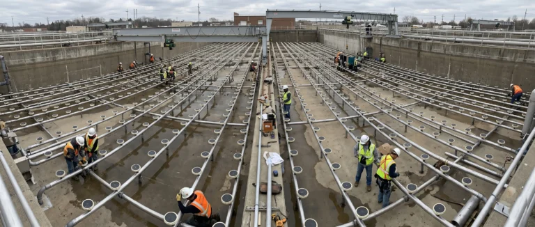
Fine bubble tube diffusers are a popular alternative to disc diffusers for wastewater aeration, particularly in narrow or deep tanks where uniform floor coverage is difficult to achieve with discs. Their cylindrical shape releases bubbles along the full length of the tube, creating a continuous curtain of fine air bubbles for efficient oxygen transfer.
Choosing the right tube diffuser — length, diameter, membrane material, and number of units — determines your aeration system’s SOTE (Standard Oxygen Transfer Efficiency), energy consumption, and the overall capital cost of the diffuser grid.
This guide covers our full range of fine bubble tube diffusers, how they compare, and how to select the right one for your project.
What Is a Fine Bubble Tube Diffuser?
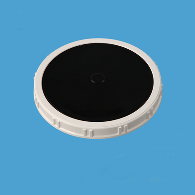
A fine bubble tube diffuser is a cylindrical aeration device installed at the bottom of a biological treatment tank. Compressed air enters the tube through a central connector and exits through a flexible membrane wrapped around the tube body, producing fine bubbles (1–3 mm) along the entire length of the unit.
Unlike disc diffusers, which release air from a single circular surface, tube diffusers distribute bubbles over a longer linear path. This makes them especially effective in plug-flow reactors, oxidation ditches, and deep tank applications where air distribution uniformity is critical.
Key components of a tube diffuser assembly:
- Membrane tube — The perforated flexible sleeve that wraps around the support core (EPDM, Silicone, or PU)
- Support core / Frame — Rigid internal structure that holds the membrane open and distributes air evenly
- End caps & connectors — Side-entry or pair-entry connections to secure the unit to the air distribution pipework
Tube vs Disc Diffusers: Key Differences
| Factor | Tube Diffuser | Disc Diffuser |
|---|---|---|
| Bubble release pattern | Linear along tube length | Circular from one surface |
| Best tank shape | Narrow, deep, plug-flow, oxidation ditches | Square, rectangular, wide basins |
| Air distribution uniformity | Even along full length | Depends on even spacing across floor |
| SOTE (typical) | 25–32% (at 5 m depth) | 28–35% (at 5 m depth) |
| Floor coverage flexibility | Good — single row can cover a long tank | Requires multiple units for uniform coverage |
| Membrane replacement | Slide off old sleeve, slide on new | Snap off old, snap on new (tool-free on some models) |
| Connection options | Side or pair-entry | Threaded base (¾" or 1" BSP) |
| Typical application | Plug-flow reactors, deep tanks, SBRs | Complete-mix basins, standard WWTP |
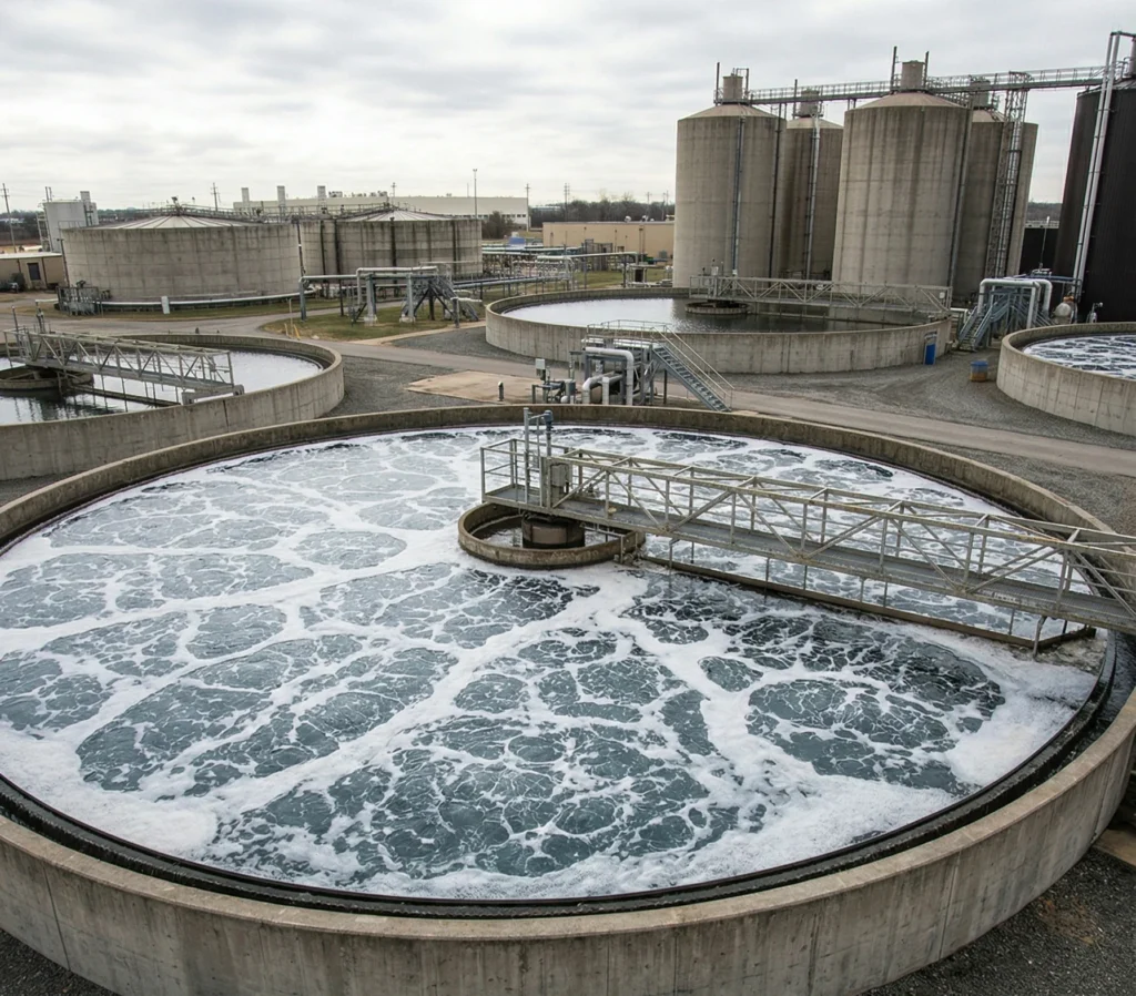
System Thinking: Tube diffusers are part of a complete aeration system. They work with air distribution piping, blowers, and control valves. A well-designed Aeration System matches diffuser type to tank geometry and process requirements for optimal efficiency.
Tube Diffuser Comparison Table
Below is a head-to-head comparison across all our tube diffuser models. Use it as your starting point, then read the detailed guidance below.
| Parameter | 500mm VX-TD-600 | 750mm VX-TD-750 | 1000mm VX-TD-1000 | 1000mm VX-TD-1000S | 1200mm VX-TD-1200 |
|---|---|---|---|---|---|
| Length | 600 mm | 750 mm | 1000 mm | 1000 mm | 1200 mm |
| Outer diameter | Ø67 mm | Ø67 mm | Ø67 mm | Ø90 mm | Ø90 mm |
| Effective aeration area | ∼0.13 m² | ∼0.16 m² | ∼0.21 m² | ∼0.28 m² | ∼0.34 m² |
| Recommended air flow | 2.0–6.0 m³/h | 3.0–8.0 m³/h | 4.0–10.0 m³/h | 4.0–12.0 m³/h | 5.0–15.0 m³/h |
| SOTE (4 mm perf, 5 m depth) | 25–32% | 25–32% | 25–32% | 25–32% | 25–32% |
| Membrane options | EPDM | EPDM | EPDM | Silicone | EPDM |
| Connection type | Side-entry | Side-entry | Side-entry / Pair | Pair-entry | Pair-entry |
| Warranty | 2 years | 2 years | 2 years | 2 years | 2 years |
| Best suited for | Small SBRs, narrow channels | Medium plug-flow reactors | Standard WWTP tube aeration | High-temp industrial effluent | Large basins, deep tanks |
Membrane Material Guide for Tube Diffusers
The same EPDM / Silicone / PU material principles apply to tube diffusers as to disc diffusers — but the tube format has a unique advantage: membrane replacement is faster. Instead of unbolting each unit, you simply slide the old sleeve off and slide a new one on, often without removing the tube from the pipework.
| Property | EPDM | Silicone | Polyurethane (PU) |
|---|---|---|---|
| Best for | Municipal & general industrial | High-temperature & aggressive chemicals | Grease, oil, solvent-laden wastewater |
| Temperature range | −40°C to 120°C | −60°C to 200°C | −20°C to 80°C |
| Chemical resistance | Good (acids, alkalis, ozone) | Excellent (most chemicals) | Excellent (oils, fats, solvents) |
| Tear resistance | Excellent | Moderate | Excellent |
| Typical lifespan | 3–5 years | 3–5 years | 2–4 years |
| Cost | $$ (standard) | $$$ (premium) | $$ (comparable to EPDM) |
Pro Tip: For most municipal applications, EPDM tube diffusers offer the best balance of performance and cost. The tube format already provides excellent air distribution — membrane material choice becomes important primarily when wastewater chemistry or temperature demands it.
How to Choose the Right Tube Diffuser
Three factors drive your decision: tank geometry (narrow vs wide, deep vs shallow), air flow requirements per linear metre (rather than per unit), and connection type (side-entry vs pair-entry determines pipework layout).
| If your project looks like... | Start here | Also consider |
|---|---|---|
| Narrow channel or SBR (<3 m wide) | 500mm side-entry | Single row covers the full tank width |
| Standard plug-flow reactor (3–5 m wide) | 750mm side-entry | 1000mm as alternative |
| Large municipal basin (>5 m wide) | 1000mm pair-entry | Two rows could be more efficient |
| Deep tank (>6 m), high air demand | 1200mm pair-entry | Fewer units at higher flow each |
| High-temperature industrial effluent | 1000mm Silicone | — |
| Retrofit replacing existing tube diffusers | Match existing length and connection type | Consider upgrading from EPDM to Silicone if process conditions have changed |
Factors That Affect Your Choice
| Factor | Why it matters |
|---|---|
| COD / BOD concentration | Higher organic load needs more surface area (Biochip) or more open media (K3/K5) |
| TSS (suspended solids) | High TSS → choose media with larger internal channels to avoid clogging |
| Reactor depth & geometry | Deeper tanks need media that fluidizes well under higher hydrostatic pressure |
| Aeration system design | Fine bubble vs coarse bubble affects the flow pattern that moves the media |
| Available space | Limited footprint → high-surface-area media (Biochip) maximizes treatment per m³ |
| Budget | K1 offers the best cost-performance ratio for most projects |
Our shortest tube diffuser. Best for narrow basins, small SBRs, and channels where space between walls is limited.
Our mid-range tube diffuser. Balances length, air flow capacity, and ease of installation. A good choice for plug-flow reactors of moderate width.
Our most popular tube diffuser length. Available in both side-entry and pair-entry configurations, with EPDM or Silicone membrane options.
Factors That Affect Your Tube Diffuser Choice
| Factor | Why it matters |
|---|---|
| Tank width & geometry | Tube diffusers are oriented across the tank width. The tube length should span most of the width, with a small gap at each wall. A 5 m wide tank typically uses 1000 mm tubes in multiple rows, or a single row of longer tubes. |
| Tank depth | Deeper tanks benefit from longer, larger-diameter tubes that can handle higher air flow and backpressure. The 1200 mm pair-entry model is the best choice for tanks >6 m. |
| Air flow per unit length | Optimal loading is typically 4–10 m³/h per metre of tube length. Overloading a tube reduces SOTE and increases membrane stress. Calculate total air flow first, then divide by tube length to get the right count. |
| Connection type | Side-entry: simpler pipework, only one connection per tube. Pair-entry: better air distribution along very long tubes, but requires pipework on both sides of the tank. |
| Membrane access for replacement | Tube membranes are replaced by sliding the sleeve off the support core. Side-entry tubes can often be serviced from one side. Plan for a minimum of 500 mm clearance at the connection end. |
| Process configuration | Plug-flow reactors benefit from tapered aeration (more diffusers at the inlet, fewer at the outlet). Tube diffusers excel here because individual rows can be valued independently. |
Installation Considerations
Tube diffusers offer some installation advantages over discs, but a few points deserve attention:
- Alignment — Tubes must be installed level and perpendicular to the air header. A misaligned tube twists the membrane and causes uneven air release.
- Spacing — Centre-to-centre spacing between parallel tubes is typically 400–600 mm, depending on tank geometry and oxygen demand.
- Header pipe placement — Side-entry tubes need the air header at one tank wall. Pair-entry tubes need headers on both sides. Plan pipework before ordering.
- Ballast / hold-down — In deep tanks with high air flow, tube diffusers may need hold-down brackets to prevent buoyancy forces from lifting the assembly.
- Drainage — The pipework should include a drain valve at the low point. When air stops, water can seep back through the membrane pores; draining prevents sediment buildup inside the tubes.
Categories
Tell us about your project
Tank dimensions, target oxygen demand, wastewater type — and we’ll recommend the right diffuser size, membrane material, and layout.
FAQ: Common Questions About MBBR Media
Are tube diffusers more efficient than disc diffusers?
Not inherently — both can achieve 25–35% SOTE at 5 m depth with properly designed grids. The real advantage of tube diffusers is linear air distribution: they provide more uniform oxygen transfer along the length of the tank, which matters in plug-flow configurations. Disc diffusers are usually better suited to complete-mix basins.
What's the difference between side-entry and pair-entry connections?
Side-entry: air enters from one end of the tube; the other end is capped. Simpler pipework, but longer tubes (>1000 mm) may have uneven air distribution. Pair-entry: air enters from both ends; requires pipework on both sides of the tank, but ensures even air distribution along the full tube length. Pair-entry is recommended for tubes over 1000 mm.
Can I mix disc and tube diffusers in the same tank?
Yes — some designs use discs under the main basin area and tubes along the walls or in narrow zones. However, the grid layout and air flow balancing becomes more complex. It’s usually simpler to choose one technology per tank unless the geometry forces a hybrid approach.
What air quality is required for tube diffusers?
Same as for disc diffusers — compressed air should be filtered to remove particles >50 microns. Oil-free blowers are strongly recommended; oil vapour clogs membrane pores and accelerates deterioration. The tube format is slightly more forgiving of particulates than discs because the membrane surface is vertical, but clean air is still essential for long membrane life.